This post explains the details of a plugin I created for Unity3D. The plugin is about to have characters looking at a target in a biomechanically correct way and using more than one bone to look at a target in world space. The plugin can be found from asset store via link below:
http://u3d.as/136L
The post is organized as follows. First, the workflow of the plugin is completely explained to help users understand the topic well. Also the blog post tries to carry an academic approach so if anyone wants to implement this feature on another platform can get an idea how to do it. Second the API and parameters of the plugin is explained so users know exactly how to use the system and at the end, important notes are provided. Make sure to completely read the section "important notes on setting up" if you don't have time to read the whole documentation.
Rotate Around Up Vector Weight:
This value shows how much a rotation should be toward character up vector. This value can be very useful for bones which has higher rank in the look at chain hierarchy for example spine bones. When Rotate Around Up Vector Weight is set to zero for a spine bone in a look at chain, the spine bone can be rotated in three directions while a human doesn’t usually rotate the spine in three dimensions to look at a target. Two pics below can show the differences:
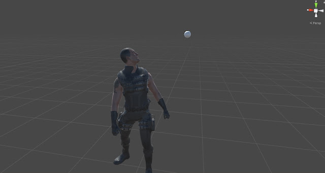
Pic above shows the character while the values for the Rotate Around Up Vector Weight is set to zero for all the bones. As you can see the spine has some extra rotations which is not quite natural. When a humanoid wants to look at a target it mostly rotates its spine in yaw axis and less in pitch and roll. This limited rotation is done to be sure the body remains balanced because spine carries a big part of upper body mass and by rotating it, the body center of mass can be changed and the character loses balance so setting this value for spine bones can help to achieve a more natural pose.
In Pic below values for the Rotate Around Up Vector is set as follows:
Eyes: 0
Head: 0
Neck: 0
Spine1: 0.1
Spine2: 0.2
Spine3: 0.7
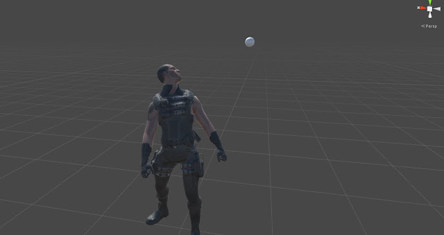
As you see in the results, the spine rotations are more natural now. To find out examples of this case please check out the three provided prefabs in the project.
Leg Stabilizers:
Make sure to check the 3 Prefab Characters and their corresponding scenes as an example of perfect look at. All 3 have different rigs and they use perfect look at. They can be found in Assets/Media/Prefabs
http://u3d.as/136L
The post is organized as follows. First, the workflow of the plugin is completely explained to help users understand the topic well. Also the blog post tries to carry an academic approach so if anyone wants to implement this feature on another platform can get an idea how to do it. Second the API and parameters of the plugin is explained so users know exactly how to use the system and at the end, important notes are provided. Make sure to completely read the section "important notes on setting up" if you don't have time to read the whole documentation.
1- Introduction
Imagine you want to write something using your computer's keyboard. When you are pressing keyboard buttons, you are mostly using your fingers and less movement comes from your arms or elbows. This shows a simple and basic rule in biomechanics, telling that if you can use your small muscles to do something, you will use them and you won't involve your big muscles in action. Using bigger muscles means consuming more energy and it's avoided on unnecessary situations. Of course using small muscles always need more focus and training. That's why you see a kid can start walking between age 1 or 2 but he can't tie his shoe laces until a reasonable age.
So let's consider another example. A pull up action. When you want to pull up your weight using a pull up bar first you use fingers to hang, then you see your fingers' tendons, ligaments and muscles are stretched and they can't hold your weight then you use your elbow and you see your elbow muscles are extended and tendons are getting stretched then you add your arms to the action and this procedure continues for your shoulders, chest and abs' muscles. So as you can see, you tried to do the action first with your small muscles and since they weren't powerful enough, you asked for help from your other muscles and managed to use your bigger muscles to finish the action.
Now let's expand this on another example. A look at example! So now imagine there is a picture in front of you. You can look at it without moving your head and just by moving your eyes. Now move the picture a few centimeters to your left. You still can look at the picture with your eyes however you feel your eyes muscles are getting stretched and tired. Now again move it a bit more to left you. Try to look at it and you see you can't look at the picture with just using your eyes because your eyes muscles are stretched completely and the picture is out of your eyes joint range so you need to use your neck and head as well to look at the picture. So continue like this and move the picture away from you and even more toward your back. You will see your head and neck joints and muscles get stretched and you need to rotate your spine and chest joints to look at the target. At the end you see that all your eyes muscles, head, neck and spine are in action to let you look at the target just like the pull up example where you couldn't just use your finger muscles to pull up your weight and lots of other muscles came into action for you to pull your weight up.
Perfect look at is working based on this rule. In perfect look at, you can define a chain of bones and their corresponding joint limits in degrees. If the first joint reaches its limit the second one starts rotating to look at the target. When the second bone reaches its limit the third one starts rotating and this procedure goes until the end of the bone chain. This way you can create a combination of bones to look at a target and not just use simple head movement. Let's have look at the results in these videos:
2- Technical Workflow
This section describes the look at procedure with details.
Every defined bone in look at bone chain has a forward vector which is used to show the bone's current direction. A target in world space is defined as the point which character wants to look at. To look at the point, the system starts from the first bone in the chain. It gets the current bone's forward vector and then calculates the rotation which can bring the bone's forward vector to the difference vector of the target point and the bone position in world space. Pic below shows the vectors.


The first bone rotates and will be clamped into its joint limit range. If the first bone meets its joint limit the second bone starts to rotate to let the first bone follow the target. Please note that the second bone should be an ancestor of the first bone. It should not be necessarily its parent but a bone in the same hierarchy which can rotate the first bone when it rotates. The same relation should go for bone two, three and so on. For example if the first bone is head, the second bone can be neck or chest because they are ancestors of the head but it can't be eye because eye is not an ancestor of head.
To rotate the next bone in the bone chain, the system needs to specify a forward vector and a target vector to find the rotation between them. The forward vector is calculated by adding the normalized rotated forward vector of the first bone and the position differences of the first bone of the chain to the current bone( all in world space ).
The target vector is calculated by adding the position difference vector from the first bone of the chain to the current bone and adding this to the normalized position difference vector of target point from the first bone position. This way, by rotating next bones in the look at at chain, we can make sure the first bone in the chain aligns to the target even if the target is out of its joint range. Just a small note here, if the first bone has a huge translation difference from the next bones in the look at chain, the final look at result might have a little error and it won't exactly meet the target but generally character will always look at the target with a good precision which can provide a good intuition of character look ats.
To rotate the next bone in the bone chain, the system needs to specify a forward vector and a target vector to find the rotation between them. The forward vector is calculated by adding the normalized rotated forward vector of the first bone and the position differences of the first bone of the chain to the current bone( all in world space ).
The target vector is calculated by adding the position difference vector from the first bone of the chain to the current bone and adding this to the normalized position difference vector of target point from the first bone position. This way, by rotating next bones in the look at at chain, we can make sure the first bone in the chain aligns to the target even if the target is out of its joint range. Just a small note here, if the first bone has a huge translation difference from the next bones in the look at chain, the final look at result might have a little error and it won't exactly meet the target but generally character will always look at the target with a good precision which can provide a good intuition of character look ats.
The same workflow continues until the first bone can hit the target or the final bone in the chain meets its joint limit.
Each joint limit is calculated based on the angle between its forward vector and its parent's forward vector. By parent I mean the exact parent in the skeleton hierarchy however the joint angle limit can be calculated easier by calculating the difference of the current bone rotation with its corresponding reference pose rotation but unfortunately Unity Mecanim is not exposing the reference pose into scripts and currently there is no way getting the reference pose. Whenever unity exposes the reference pose into the scripts, both the bone forward vector and parent forward vector will be removed and the reference pose forward vector will be used instead to provide an easier setup for users.
3- Perfect Look At Component Properties
Up Vector:
Up vector shows the character’s world yaw axis which is set to engine’s up axis by default. This vector is used as an axis for “Rotate Around Up Vector Weight”. When “Rotate Around Up Vector Weight” is set to one the bone just rotates around up vector and for any values less than one, the axis blends between the original rotation axis and the up vector axis.
Target Object:
A game object used as the target object for the system. Characters with perfect look at component will look at this object.
Look At Blend Speed:
This value shows how fast the current look at pose will be blended in from the last look at pose. This smooth blending can be very helpful specially when look at is applied on top of a dynamic animation which has a lot of movement.
Leg Stabilizer Min Distance To Start Solving:
This value is used for
leg stabilizer feature. If the difference between feet bone before and after
applying perfect look at is more than this value the system tries to fix the
feet to avoid any foot sliding. The difference is more than zero if any of the
parent bones of the “foot bone” changes rotation by perfect look at. If you set
this value to a high value it can cause jitters on legs. If the value is zero
the leg stabilizer is always called. It’s recommended not to change this value from
its default unless it’s needed.
Please check the Leg
Stabilizers section to find out more about the feature.
Leg Stabilizer Min Distance To Start Solving:
Leg Stabilizer Max Iterations:
Leg stabilizer uses
FABRIK IK solver to avoid feet sliding. This value shows the maximum number of
iterations to solve the IK solution. It’s recommended not to change this value
from its default if your character has 3 or 4 leg joints. For character more
than 4 leg joints the recommended value is 30.
Please check the Leg
Stabilizers section to find out more about the feature.
Draw Debug Look At:
If checked, target vectors and forward vectors for each bone is drawn in scene viewport. Target vectors are drawn in red and forward vectors are green.
Look At Bones:
An array of look at bone data. The size of the array should be equal to the number of bones you want to get involved in the look at process. Make sure there would be no missing bone in the array unless the systems prevent itself from working.
Bone:
The look at bone which is going to be rotated to look at the target.
Rotation Limit:
Joint limit in degrees. If the angle difference between the current bone and its parent in the skeleton hierarchy is higher than this value the next bone in the "Look At Bones" array starts rotating to help the first bone reach the target.
Rotate Around Up Vector Weight:
This value shows how much a rotation should be toward character up vector. This value can be very useful for bones which has higher rank in the look at chain hierarchy for example spine bones. When Rotate Around Up Vector Weight is set to zero for a spine bone in a look at chain, the spine bone can be rotated in three directions while a human doesn’t usually rotate the spine in three dimensions to look at a target. Two pics below can show the differences:

Pic above shows the character while the values for the Rotate Around Up Vector Weight is set to zero for all the bones. As you can see the spine has some extra rotations which is not quite natural. When a humanoid wants to look at a target it mostly rotates its spine in yaw axis and less in pitch and roll. This limited rotation is done to be sure the body remains balanced because spine carries a big part of upper body mass and by rotating it, the body center of mass can be changed and the character loses balance so setting this value for spine bones can help to achieve a more natural pose.
In Pic below values for the Rotate Around Up Vector is set as follows:
Eyes: 0
Head: 0
Neck: 0
Spine1: 0.1
Spine2: 0.2
Spine3: 0.7

As you see in the results, the spine rotations are more natural now. To find out examples of this case please check out the three provided prefabs in the project.
Forward Axis:
The forward vector of the bone. To find the forward axis of a bone, first you need to turn the coordinate system into local then you need to select the bone from the hierarchy panel. Afterwards you can find the forward vector. Picture below shows an example how to find the forward vector of the head bone for a character. As you can see the forward vector for this bone is Y-Axis:


Parent Bone Forward Axis:
The forward vector of the current bone's parent. To find the forward axis of the parent bone first you need to turn the coordinate system into local then you need to select the bone's parent from the hierarchy panel. Afterwards you can find the forward vector. Picture below shows an example how to find the forward vector of the head's parent bone which in this case is neck. As you can see the pic below, neck's forward vector is Y-Axis:


Reset To Default Rotation:
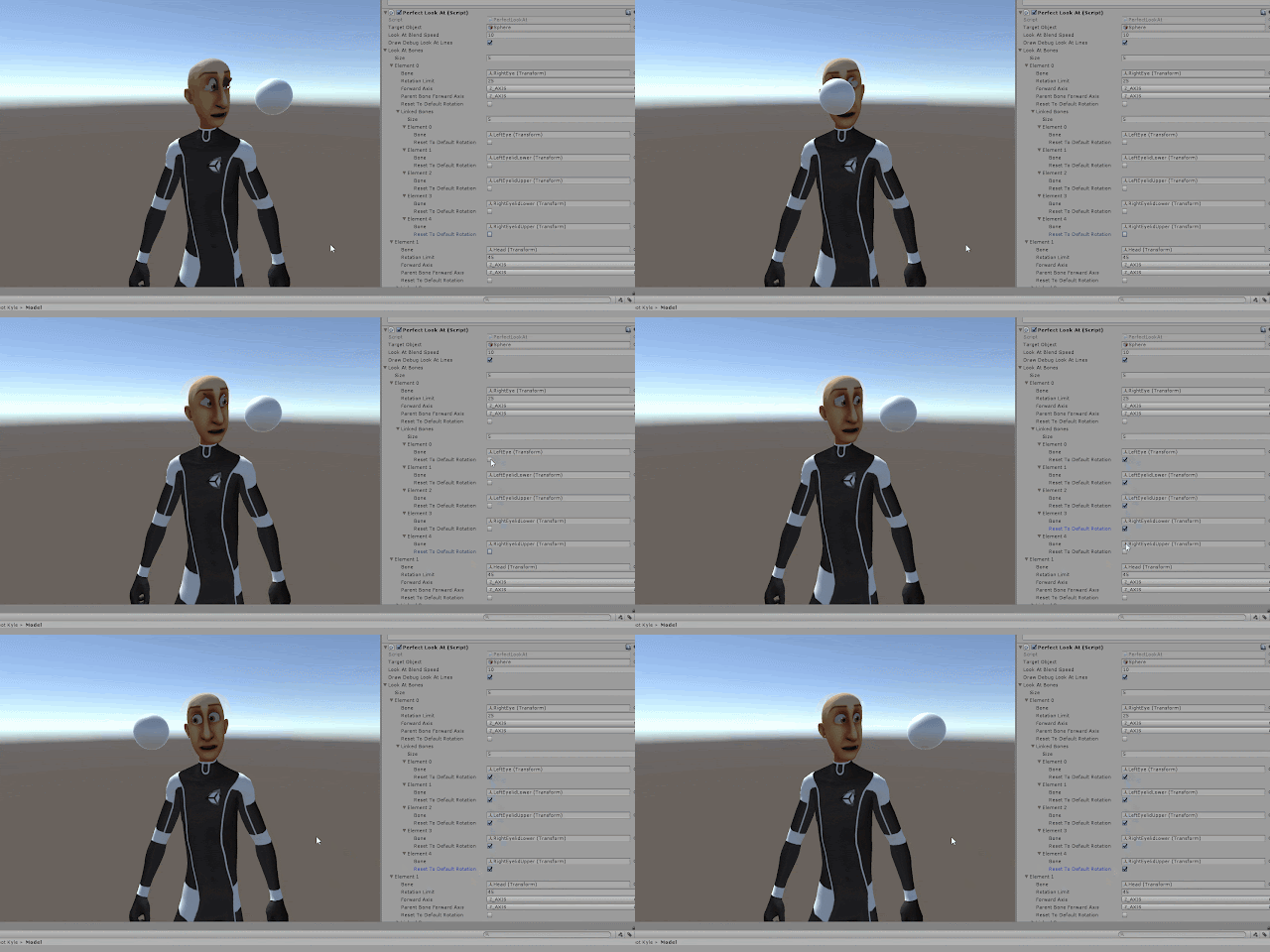
In Unity Mecanim, when an animation is retargetted on a different rig, if that rig has more bones than the retargetted animation, those bones never get updated to any specific transform. This mean they always use a cached value of the last valid transformation they already received and the pose buffer never gets flushed which sometimes makes problems. To avoid having this situation, make sure to check the "Reset to Default Rotation". Check this check box only when you are sure the look at bones don't receive any pose from the current animation otherwise leave this check box unchecked. Check out the two GIFs below to find out the differences:

As you can see in the GIF above the spine remains disconnected because it receives no pose from animation and it uses the last valid cached pose. By checking the Reset To Default check box we can create a valid rotation for the bones which don't have any animation but want to be in the look at bone chain.


As you can see in the GIF above the spine remains disconnected because it receives no pose from animation and it uses the last valid cached pose. By checking the Reset To Default check box we can create a valid rotation for the bones which don't have any animation but want to be in the look at bone chain.

Linked Bones:
Linked bones are the bones which should be rotated as same as the current bone. For example, one look at bone chain can be created like this:
Lookat Bone 1 = Right Eye
Lookat Bone 2 = Head
Lookat Bone 3 = Neck
Lookat Bone 4 = Spine2
Lookat Bone 5 = Spine1
Lookat Bone 6 = Spine0
As you can see, there is no Left eye here. So if you apply this look at bones chain to the character, all the bones can be rotated based on their joint limits but the left eye remains still. Here we can define left eye as a linked bone of the right eye. So wherever right eye rotates, left eye also rotates with it. Just like a linked transform. You can add as many as linked bone you want to the current bone.
To find examples of linked bones check out HumanCharacter and UnityCharacter prefabs in the project.
Linked Bones-Reset to Default Rotation:
This is exactly the same as Reset To Default Rotation in the LookAtBones. If you face some situations like the GIF below when you add linked bones, this means the linked bone doesn't carry any animation info and you need to check the Reset To Default Rotation for the bone to make the Mecanim pose buffer not to use the invalid poses.

Leg Stabilizers:
If there is a bone in chain of look at bones which is the parent
of legs, then by rotating that bone the legs can slide on the ground. For example
in a humanoid character you can set these bones for look at chain: eyes, head,
neck, spine2, spine1 and pelvis. Since the pelvis is the parent of thighs by
rotating it the legs start rotating and the feet start sliding on ground. This
issue can be avoided by setting leg stabilizer. Leg stabilizer set the feet and
knee exactly like original animation so rotating the pelvis won’t slide the
legs and won’t twist the knees. This feature can be useful for quadruped
characters as well. The feature fixes the knee angle and feet position based on
original animation to save the fidelity to original movement.
As an example, please check out Human and Unity Character prefabs
in the project.
Foot Bone:
The bone that needs to be stabilized when one of its parents are
rotated by perfect look at. It usually is the foot bone. This will be the end
effector of the IK chain defined by leg stabilizer.
As an example, please check out Human and Unity Character prefabs
in the project.
IK Weight:
If this value is set to 1, the selected bone will be completely constrained to IK and get stabilized completely. If set to, it 0 will be completely free from IK and no feet stabilization happens. Any value between 0 and 1 makes an average out of stabilized IK feet and free FK feet. You might need to change the weight value based on some gameplay events. For example there is no need to stabilize feet when the character is falling so the weight can be set to zero in such a case.Bones Count:
The number of bones to be added to the Leg stabilizer IK chain.
For example for a biped character it should be 3. The first bone is the foot
bone which already set in the foot bone slot, second is the calf and the third
is the thigh. The system automatically gets the parents of the Foot Bone and
add them to the IK solver.
As an example, please check out Human and Unity Character prefabs
in the project.
4- Perfect Look At Component Public API:
GetLookAtWeight():
Returns the current weight of the perfect look at. If weight is zero, perfect look at is turned off, if one perfect look at is applied 100% and any value between will make an average between animation and procedural rotation provided by perfect look at.
SetLookAtWeight( float weight ):
Sets the current weight of the perfect look at. Please note if you use this function any transition will be cancelled because Perfect Look At is not letting external systems to change the weight in two different ways. By two different ways I mean setting look at weight manually or by calling Enable/DisablePerfectLookAt.
This cancelling is provided to avoid having an error-prone pipeline. To find out more about transitions, check out EnablePerfectLookAt and DisablePerfectLookAt.
This cancelling is provided to avoid having an error-prone pipeline. To find out more about transitions, check out EnablePerfectLookAt and DisablePerfectLookAt.
EnablePerfectLookAt( float time, bool cancelCurrentTransition = true ):
If this function is called, perfect look at's weight will turn into one within the specified time (blending in).
cancelCurrentTransition: If set to true and if another call to this function or DisablePerfectLookAt is made and the system is still on the transition, the current transition time will be set to zero and transition will continue from current weight to the destination weight within the new time specified.
If cancelCurrentTransition is false and if the system is on a transition, any other call to DisablePefrectLookAt or EnablePerfectLookAt will be ignored.
DisablePerfectLookAt( float time, bool cancelCurrentTransition = true ):
If this function is called, perfect look at's weight will turn into zero within the specified time. All other details are the same as EnablePerfectLookAt. Please refer to EnablePerfectLookAt to find out more about the function parameters.
IsInTransition():
If PerfectLookAt is on disabling or enabling transition, it will return true otherwise false.
GetTimeToFinishTransition():
If PerfectLookAt is on disabling or enabling transition, it returns the remaining time to finish transition.
Important Notes on Setting up Perfect Look At:
Perfect Look At is a component. To use it, it's just needed to be assigned to a game object. Some important cases to use Perfect Look At is addressed here:
1- Turn Off Optimize Game Objects:
The only way to change bones transformations in a procedural way in Unity, is through LateUpdate of a component. Unfortunately Unity won't let you set the bones transforms if the "Optimize Game Objects" option of a rig is checked. To make PerfectLookAt working you need to be sure "Optimize Game Objects" is not checked. There is no info on Unity documentation why it is impossible to transform bones in an optimized rig and how Unity Optimize the skeleton calculations.


2- Setting Reset To Default Rotation On Some Necessary Cases:
If you see any of the linked bones are rotating constantly make sure you turn the Linked Bone's Reset To Default Rotation on. To find out more why this issue is happening please refer to Reset To Default Rotation section in this documentation.
3- Defining the Forward Axis of The Bones and Their Corresponding Parents Correctly:
Make sure you always select the correct forward axis both for the bone and its parent. Make sure you change the coordinate system to local and see the bone and its parent's forward axis in the local coordinate system. For more info please check out "Forward Axis" and "Parent Bone Forward Axis" section in this document.
4- Look At Bones Should Be In The Same Hierarchy But Not Necessarily Child and Parent:
Look at bones order in the "Look At Bones" array matters. It should be set based on the bones hierarchy. For example 4 bones( two eyes, head and chest ) are needed to rotate using perfect look at. These 4 bones should be specified in this order:
First Bone: Left eye ( its linked bone should be right eye )
Second Bone: Head
Third Bone: Chest
As you can see, bones defined here are not necessarily parent and child but they are in the same hierarchy. For example Chest is the parent of neck and neck is the parent of head. So when Chest rotates, head will also rotates.
5- Checking Character Prefabs as an Example:
Make sure to check the 3 Prefab Characters and their corresponding scenes as an example of perfect look at. All 3 have different rigs and they use perfect look at. They can be found in Assets/Media/Prefabs


